PlonK Deconstructed: Arithmetization


Hey, nice to see you have decided to continue with the blog series. As promised in this part, we try to convert a circuit into a set of equations. Ultimately we would want to convert the program into a set of polynomials and arithmetization is one of the crucial steps to get there.
This post explains PlonK-based arithmetization, but there are also other approaches like R1CS. One more important disclaimer. In this series, we will consider only unary and binary gates (one or two inputs) for the sake of simplicity. However, it is possible to create also more complex custom gates.
Gate equations
As in every other PlonK explainer, we will also show the process of arithmetization on an example circuit. Consider a circuit for computing $(x_1 + x_2)(x_2s_1)$ where $x$ are public inputs and $s$ is a secret number, which only the prover knows. Since we know that there are at most binary gates, we can think of each gate as a row of a table, where columns are in order: left input, right input, and gate output. The $gate_0$ has left input $x_1$, right input $x_2$ and output $x_1 + x_2$.
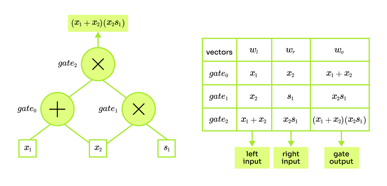
The objective is to efficiently encode an arithmetic circuit into a set of polynomials. The first step will be to encode each gate as an equation. Later in the setup phase, we will combine these equations into polynomials. Considering only gates for addition and multiplication each gate could be written as one of the following:
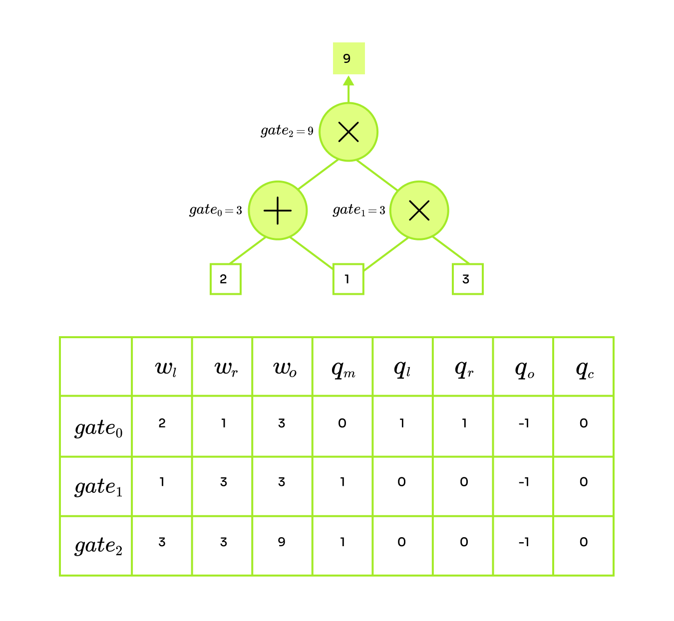
$$\text{\textit{addition:} } \text{left input} + \text{right input} = \text{gate output}$$ $$\text{\textit{multiplication:} } \text{left input} \times \text{right input} = \text{gate output}$$That is a good start, but it would be even nicer if we could create an equation that can check the validity of both gate types. Notice that each column of the computation table could be also viewed as a vector. By assigning $x_1 = 2, x_2 = 1, s_1 = 3$ we would get vectors $w_l = [2, 1, 3], w_r = [1, 3, 3], w_o = [3, 3, 9]$. These numbers represent the whole computation of the program and in the context of PlonK, they are referred to as the witness. So, in the end, witness are just vectors of a bunch of numbers. For the rest of the posts, we will denote $n$ as the size of the circuit which is the number of gates in the circuit.
Besides, we also need something to specify the type of the gate and this is done by selectors: $q_l$ left, $q_r$ right, $q_o$ output, $q_m$ multiplication, $q_c$ constant. These are vectors of size $n$ selecting the type of gate which we want to use. For example, if we are dealing with gate $i$ that is a multiplication gate then $q_{m_i} = 1$ otherwise it is always set to 0. Now we will introduce an extended equation for gate number $i$. This equation makes sure that each of the gates is computed correctly. To verify the multiplication gate we need: $w_{l_i}w_{r_i} = w_{o_i}$ and to verify the addition gate $w_{l_i}+w_{r_i} = w_{o_i}$. We will combine these two and show how to assign the selector to pick the type of gate we want to use.

Consider the example circuit and variable assignment $x_1 = 2, x_2 = 1, s_1 = 3$, and for simplicity, all unassigned selectors will have 0. It is possible to perform these operations:
-
addition: $q_{l_i} = q_{r_i} = 1, q_{o_i} = -1$
For the addition gate, want to keep only the addition and output terms of the equation the rest will cancel out thanks to the remaining selectors being 0. Let's illustrate it on an example circuit and construct the equation for an addition gate $gate_0$:
$$2 \cdot 1 \cdot 0 + 2 \cdot 1 + 1 \cdot 1 + -1 \cdot 3 + 0 = 0$$ $$2 + 1 -3 = 0$$ $$2 + 1 = 3$$ -
multiplication: $q_{m_i} = 1, q_{o_i} = -1$
To engage a multiplication gate we assign the selector such that only the multiplication and output terms of the equation remain. Below is the gate equation for multiplication gate $gate_1$:
$$1 \cdot 3 \cdot 1 + 1 \cdot 0 + 3 \cdot 0 + -1 \cdot 3 + 0 = 0$$ $$1 \cdot 3 -3 = 0$$ $$1 \cdot 3 = 3$$ -
constant assignment:
Besides the operations of addition and multiplication, it is possible to do constant assignments (not illustrated on the example circuit). Say that we want the left input of a $gate_i$ to be equal to some constant $c$. To construct the equation for this gate we can assign $q_{l_i} = 1, q_{c_i} = -c$, and the equation then simplifies to $w_{l_i} = c$, checking exactly what we want. This work respectively also for the right input we just set the selectors as $q_{r_i} = 1, q_{c_i} = -c$.
Notice that using the selectors some terms are canceled out so that we get to the separate gate constraints described above. To better see how the selectors should be assigned for the example circuit check the diagram below.
The vectors $w_l, w_r, w_o$ encapsulate all of the values flowing through the circuit, where some of the values are public and some are secret. The verifier needs to check the correctness of the output of the circuit and the public input, so naturally, these two will be public. The rest of the values remain private.
To get the full gate equation we add one last thing. The public input to the circuit will be denoted by vector $PI$. The vector $PI$ can be changed for each execution of the circuit while the constants $q_c$ (unsurprisingly) remain bound to a specific circuit. The full equation that checks computation of gate $i$ looks like this:
$$w_{l_i}w_{r_i}q_{m_i} + w_{l_i}q_{l_i} + w_{r_i}q_{r_i} + w_{o_i}q_{o_i} + PI_i + q_{c_i} = 0$$Let's revise this on the Sudoku game. Imagine the prover is trying to convince the verifier that he knows the solution to some Sudoku. The circuit is a program that checks if the Sudoku is filled validly and the prover wants to show that he can fill in such numbers that this program accepts his solution. Here the public input is the initial state of the Sudoku as well as the dimensions of the board. Naturally private witnesses are the numbers that need to be filled. We should also mention that there is a convention that the correct result of the circuit should be 0. That is the same as saying the output of the program is 0 if it succeeds.
Circuit Check
With an equation for each gate, we can encode arbitrary circuits with addition and multiplication gates. The following objective is to convince the verifier that we know such a secret witness, which makes the circuit output 0. Sounds easy? Well we need to guarantee the integrity of the whole computation. Since there are numerous ways to cheat, the prover needs to show the following:
input check: promised public inputs were provided to the circuit
gate check: gate equation holds for each gate
wiring check: wires are plugged in correctly (wires are the connecting lines)
output check: output of the circuit is 0
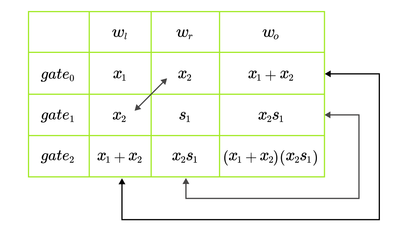
Most of the checks are descriptive, besides the wiring check. Considering the example circuit, this check ensures that outputs of $gate_0, gate_1$ are indeed provided as inputs to $gate_2$. This is also referred to as copy constraints because we want to make sure that the output of some gate is correctly copied to the input of another gate. This can also be nicely seen on the computation table, where the cells connected by arrows should be equal.
In conclusion, you should be convinced that each arithmetic circuit with gates $\{+, \times\}$ could transformed into a series of equations. However, this transformation into equations could go wrong in many ways and that is why the prover needs to construct the proof. This proof is ultimately an argument of knowledge because if the circuit outputs 0, the prover must know the secret information. There is one more topic to discuss before we look into the PlonK polynomial magic. That is polynomial commitment schemes, specifically KZG. But even before that you might want to look at the Math Toolkit for KZG.
List of the PlonK blog posts: